
Recently I witnessed an interesting occurrence on the line that has resulted in a number of queries to Boeing, and while not all the answers are back, the results so far are fascinating. Eighteen years on the aircraft and still learning, which is actually a nice place to be.
Disclaimer : Normally I try to produce content to engage readers across the spectrum from those with an interest in Aviation through avid Simmers through to other Professionals operating the 777. In this case, the following is unashamedly technical and I apologise if I lose you on the way through – each time I re-read it, I lose myself and change it again!
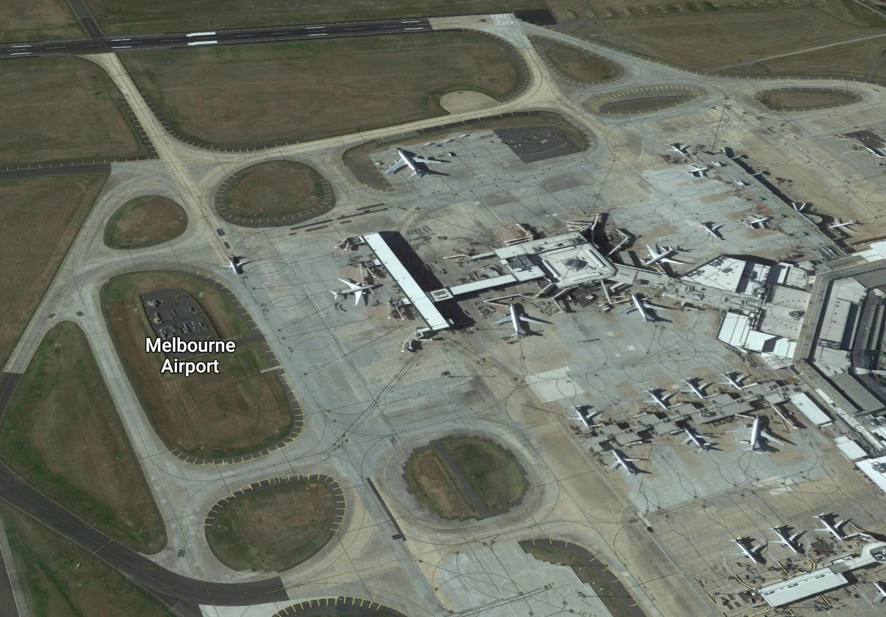 We were parked on stand in Melbourne (YMML; Stand D20) getting ready to go to Los Angeles and while the ambient temperature was 19° and a light northerly blowing, we were heavily loaded and full thrust was going to be required – Melbourne has some hills to the north which reduces the weight you can lift, despite a small headwind component. As the temps get higher in Melbourne, you can get into a weird situation where you’re better taking a small tailwind away from the hills off Runway 16 than a small headwind towards them on Runway 34 – but I digress … for this sector, I was in the jumpseat, conducting an Annual Line Check on the two operating crew members.
 During entry of the takeoff performance into the FMC (Flight Management Computer) by the Captain, I noted a disparity between the N1 specified by the Takeoff Performance Calculation (TLDC); and that calculated by the Flight Management Computer.
While the TLDC (Takeoff Landing Data Calculator – the computer software we use to calculate takeoff and landing performance) calculates the N1 that we’ll be using for takeoff – in actuality, the performance calculation specifies a Fixed Thrust Rating (TO, TO1 or TO2) in combination with an Assumed Temperature value.
We enter these TLDC calculated Thrust Selections into the FMC and in conjunction with the entered weight and aircraft systems sensed ambient conditions (temperature, pressure) – the FMC calculates the target N1 for takeoff.
There is almost always a small difference between the value calculated by the FMC and that calculated by the TLDC computer. This comes down to several factors, one being that the Airconditioning Packs prior to takeoff are working at full capacity; whereas they are reduced to a low flow rate during the takeoff roll. This leaves more thrust available for the engine, resulting in a different N1 calculation result. The TLDC computer is aware this is going to happen and calculates accordingly; the FMC modifies the Target N1 once the Packs are reduced during the roll.
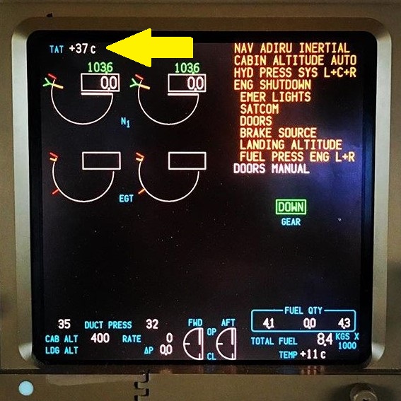
 On this day – the difference was more than “normal” – about 1.5% with the FMC calculating a lower value (which typically calculates a slightly higher value). Our SOPs note the difference but have no crosscheck or tolerance as such. In the past, I’ve seen this occur when the ambient temperature is higher on the aircraft gauges than the Airport Weather Service (ATIS) is giving. While we use the ATIS reported temperature in our (TLDC) calculations for N1; the FMC can only repeat the calculation of N1 by referring to the temperature “felt” by the aircraft and reported through the TAT (True Air Temperature) probe. In this case – the TAT indication on EICAS was 37° as against the ATIS 19°. That explained the N1 difference – but not why the TAT indication was so high.
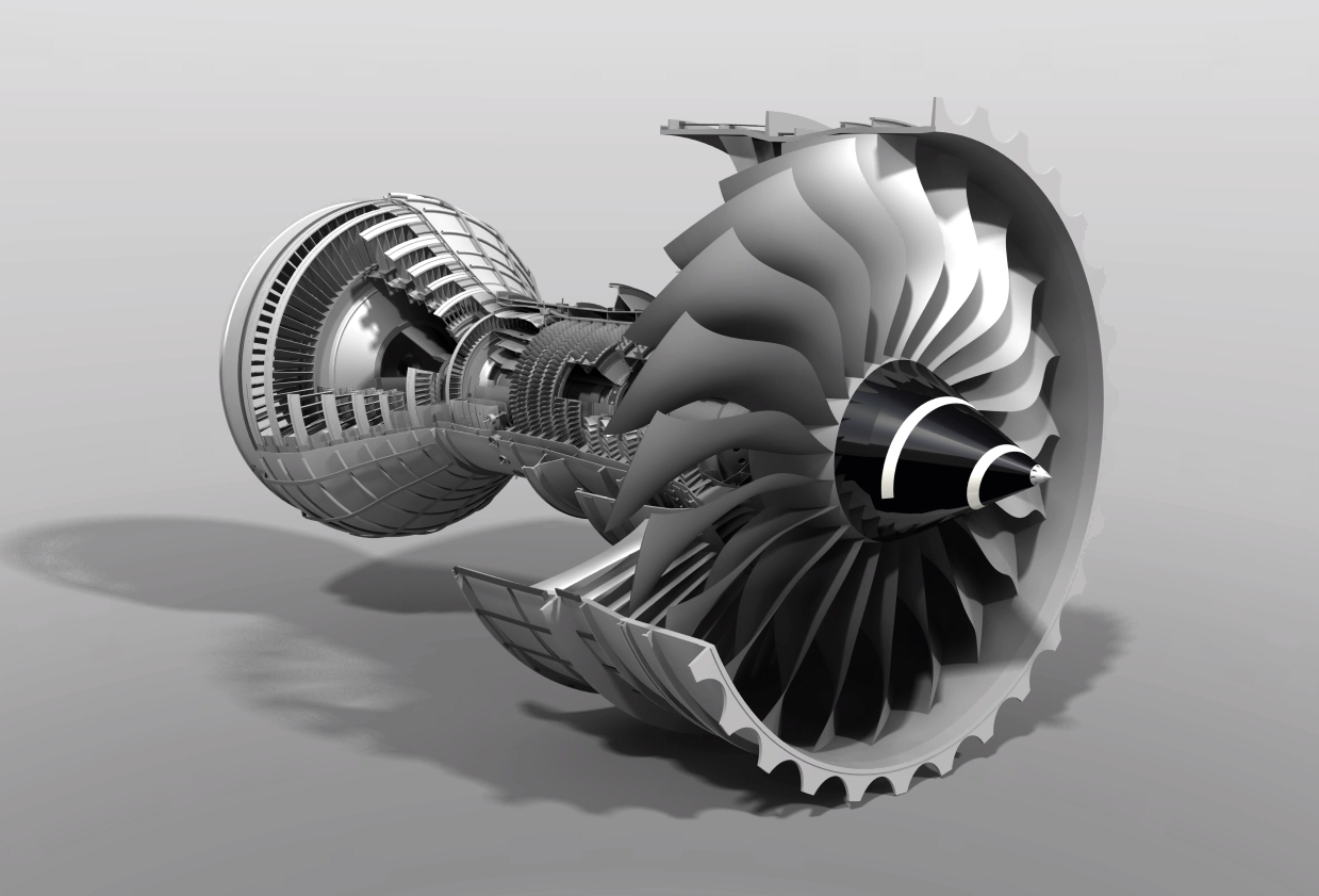
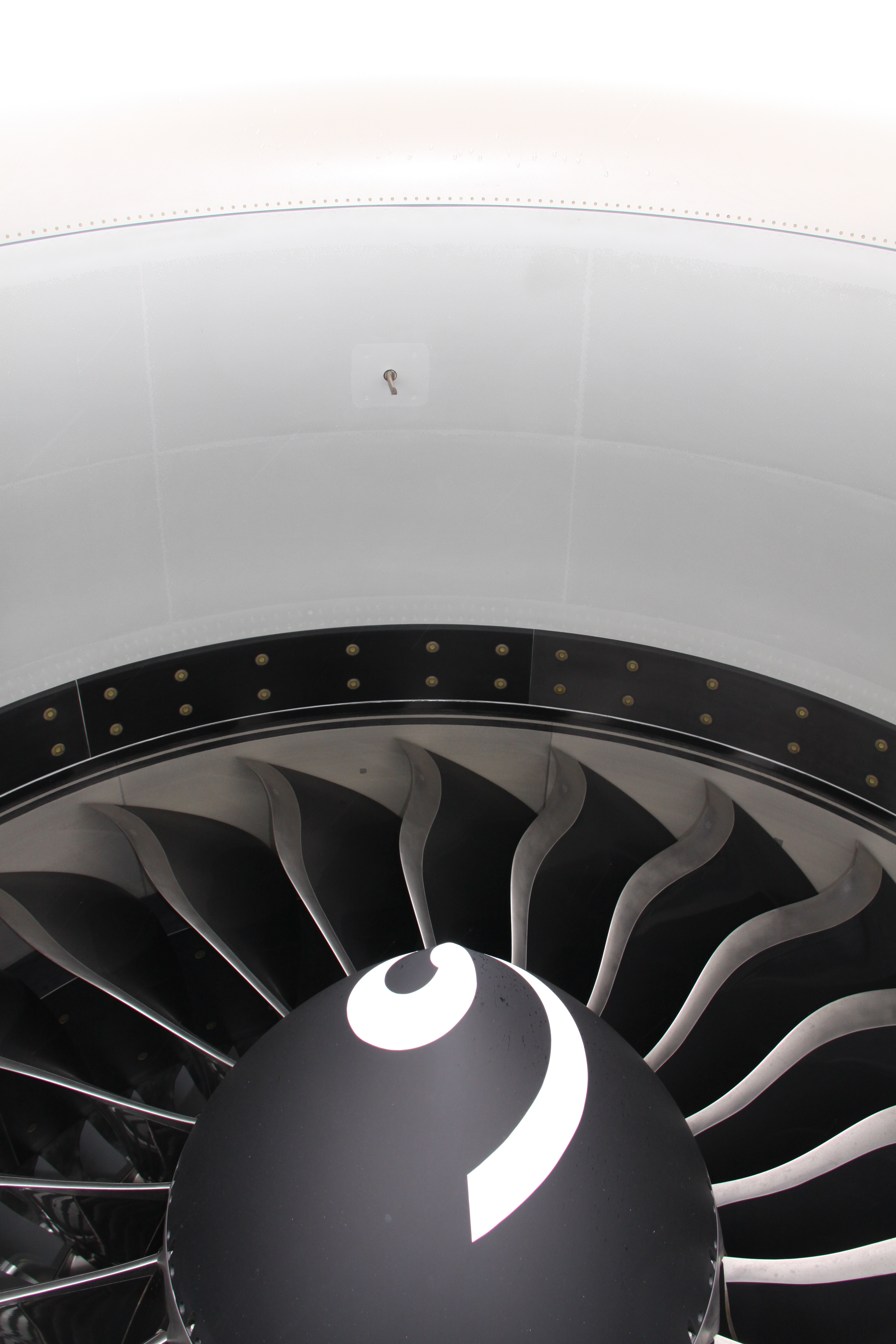
“N1” is engineering nomenclature used to refer to the rotation speed of the First Rotor – in our case the big fan you see at the front. Broadly speaking the rate of spin of this fan is equivilated (another engineering term) to Thrust. The GE90’s have two engine spools, the second of which is (of course) called the N2. The 777-200’s I used to fly had Rolls Royce Engines with three spools, so of course, there was an N3. On modern high bypass engines, the N1 is essentially a huge fan (not terribly dissimilar to the Propellors of old), rotates the slowest, produces most of the actual thrust, and is driven by a connected turbine in the exhaust gas flow at the rear of the engine. The N2 (and N3) spools are all about compressing the air (intake) and extracting energy from that air on it’s way out the back end after that air is burnt in the depths of the engine casing.
N1, N2 and N3 values are given as percentages (for example Red Line Maximum N1 for the GE90’s in my aircraft is 110.5%) because their spin rate differs vastly. The big fan at the front averages 4000 RPM during takeoff; the little one in the middle closer to 13,000. As to why maximum speed is not 100% – I really have no idea, it’s never made sense to me for them not to callibrate things that way. It just is.
The Captain remarked on the N1 difference and we noted the high TAT reading. I’d seen this before when parked and airflow is poor through the TAT probe; but we were facing the Terminal (East) and the probe was actually in shadow, so it still seemed odd. We resolved to re-examine the TAT during aircraft push and engine start; hopefully, the TAT indication would assume a more appropriate value.
TAT is the measure of Total Air Temperature, as measured by a dedicated probe on the outside of the flight deck (Aircraft TAT) or just inside the top of the two engine nacelles (Engine TAT). It’s called Total Air Temperature because at speed the temperature measured reflects the combination of Outside Air Temperature (OAT, somtimes referred to as Static Air Temperature, SAT) and the temperature rise that occurs when air molecules are smashed against a fixed probe racing through the atmosphere at 800 kph. At 35,000 ft the OAT can be -56°C wheras the TAT can 20-30° warmer.
On the ground, the TAT indication is considered a valid measure of OAT, but caution has to be exercised if you’re going to use it to second guess the airport ATIS temperature. The temperature reported by the ATIS is essentially a certified value, taken at a specific location, behind a Stevenson Screen, monitored, crosschecked, etc. The TAT probe … is not.

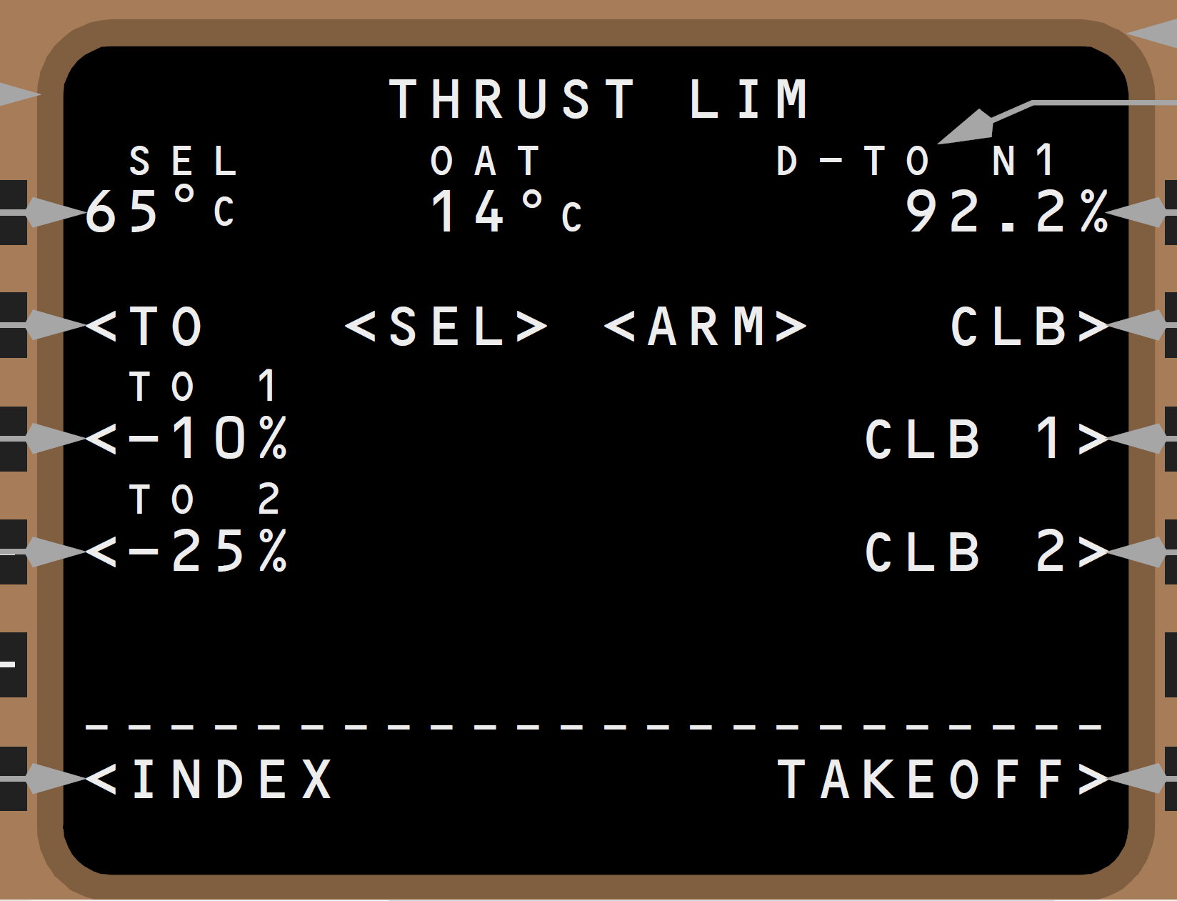
Meanwhile, I started to think about the problem of the numbers we were seeing and what impact it might have if the TAT did not drop down. The TLDC had told us that MaxT (the maximum temperature we could accept to be able to take off with our present load) was 29°, so it seemed to me that the TAT remaining well in excess of that was likely to cause us problems.
Engine start and aircraft pushback did not actually improve things:
- During Engine Start, that TAT indication remained high.
- After Start, we received an FMC Scratchpad Message V SPEEDS UNAVAILABLE (“For certain high thrust/low gross weight takeoff conditions, FMC VSPEEDS are not calculated. Adjust gross weight and/or takeoff thrust limit to enable VSPEEDs.“)
- Our previously entered speeds remained in the FMC and displayed correctly on the PFD.
- The FMC CDU Thrust Limit Page was basically completely blank (headings only)
- The Target N1 was removed from the EICAS N1 displayed.
But the temperature had dropped a few degrees with the Engine Start, so we decided to continue the scenario (looking behind us to make sure there was no Sim Instructor and this was not a Simulation …) and commenced taxi. During taxi, the TAT indication continue to reduce.
As it dropped below 28° …
- The CDU cleared the V SPEEDS UNAVAILABLE message, replacing it with “TAKEOFF SPEEDS DELETED” and our Takeoff Speeds dropped out of the FMC
- The previously selected Thrust calculations returned to the CDU Thrust Limit page and the EICAS N1 gauge.
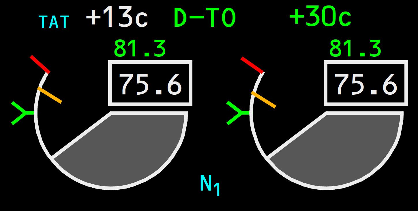 We re-entered our performance data from scratch, double checked everything and proceded for a normal departure. As we commenced the roll I noted that the EICAS was targetting an N1 of 105.5; whereas the TLDC had recommended 105.2 – which seemed pretty reasonable. Interestingly while the TAT had reduced on taxi down to the ambient 20°; it then began to increase while we sat at the holding point and re-entered the takeoff performance. During the takeoff, it reduced once again with airflow until increasing again as is normal with increasing airspeed. The FMC N1 target adjusted accordingly to these variations.
As a footnote – we became airborne normally and survived.
As is often the case – the follow up has been informative and not completely satisfying. I pursued this with our Technical Department, a contact at Boeing Propulsion, and the Flight Training/Standards and Technical Departments at three other 777 operators. So far, I have the following:
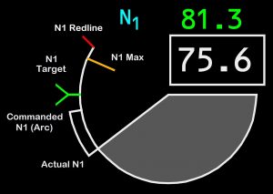 The N1 gauge on EICAS includes a Red Line Limit (maximum rotation 110.5%); the Amber N1 Max; the Green N1 Target; the White Arc N1 Commanded; and the White Line N1 Actual.
- The N1 Amber indication represents N1 Max – the max rated value of the N1 for the current flight conditions. This is the value that would be commanded if the thrust lever is placed at the max forward position, as limited by the EECs (Electronic Engine Control) operating in Normal Mode.
- The value of N1 Max, Commanded N1 and Actual N1 (to a lesser extent*) is computed by the EEC using the selected TAT source, which is normally the aircraft TAT (as displayed on EICAS) as long as it is within 2.5° of the engine TAT. In the case of a large disagreement (>5°), the EEC will select its own onside engine TAT sensor in the calculation of N1 Max. Between these two values, the selected EEC value linearly ramps the value used towards the engine source. The value of 2.5° was selected as it corresponds (on a hot day) to an amount of thrust error that is small enough preserve the acceptable operation of the engines.
- If the EECs are in Hard Alternate Mode, the EEC computed N1 Max is set to invalid, so the displayed N1 Max is subsequently computed by the TMF (Thrust Management Function) of the FMC – using aircraft TAT.
- On takeoff, after 80 knots (at a constant thrust lever position) the Commanded N1 automatically changes as temperature airspeed and then altitude increases after liftoff. The EEC and TMF both calculate the N1. The TMF target (Target N1), the EEC Commanded N1 vary automatically during the takeoff as a function of airspeed and altitude. There are a number of considerations such as engine temperature/pressure and other factors that determine the precise N1 variations to provide optimum performance and engine life.
- As such, the aircraft TAT is used throughout the takeoff to determine the N1 values by the TMF and the EEC.
- * In most cases, the Actual N1 is independent of sensed TAT in the thrust lockout period during takeoff, but it is possible for a significantly elevated TAT (such as during a Temperature Inversion) to affect the indicated N1 as well. Note that engine TAT sensors are not used to compute the TMF N1 Target.
- There is a cross-check between Aircraft and Engine TAT – if the difference exceeds 15°, then the air data is declared invalid for use by FMC and TMF, the thrust ratings will go away, the CDU Thrust Limit page will blank, and there will be no performance predictions.
- There is also some magic going on in the conversion from “corrected” N1 to “physical” N1 that is relevant to this discussion, but I’ve yet to find any clear definition of what’s going on with that. More magic I presume.
What does all this mean? Good question. As far as I can determine, the above summarises into:
- Target N1 is calculated by the FMC and is dependant on Aircraft TAT.
- Commanded N1 and Actual N1 are calculated by the EECs, which use the Aircraft TAT unless the difference between Aircraft and Engine TATs become significant, in which case the EECs bias towards – and then slave off of – the specific Engine TAT probe.
- All the values of N1 Max, N1 Target, N1 Command and N1 Actual are subject to the influence of a false TAT reading to one degree (!) or another.
- A false reading of more than 5 degrees in the Aircraft TAT would impact the N1 Target, but not Commanded/Actual N1
- A false reading of more than 5 degrees in the Engine TAT would affect the EEC Commanded and Actual N1 (affected engine), but not the Target N1.
- There’s a whole lotta magic going on
In the aftermath of this, I notified Engineering and while I lost track of the story, I believe another crew experienced a similar occurrence and a problem with airflow through the TAT probe was identified, and corrected. What is impressive in all of this is how well thought out the system involved is, and the technical depth and forethought that goes into account for all the possible things that might go wrong in something as crucial as calculating thrust for takeoff. It speaks to decades of experience in development at GE and Boeing, and it’s awesome.
Ken.
If you find my content useful and are in a position to do so – I would appreciate a contribution to my PayPal account (ken.pascoe@gmail.com) – If you use the Friends and Family feature in PayPal it reduces the charges to the transfer. Please note that when sending money in this way you are removing any form of purchase protection, which is not relevant to a contribution of this type anyway.