
A while ago I scheduled a temperature inversion in a simulator session in preparation for our operation to Abu Dhabi’s summer. For further reflections see Performance Limited Takeoff and High Temperature Departure Abu Dhabi.
The issue of temperature inversions and the implications for takeoff performance calculation raised so many issues that I ended up having to remove the sequence from the session. I set about reviewing what the industry had in this area – particularly as relates to practice and procedure for dealing with reported temperature inversions.
There ain’t much. The theory is all there of course, covering the various mechanisms under which LLTIs (Low Level Temperature Inversions) are formed; their association with Windshear; the likely effect on performance. But when it comes to dealing with them practically …
Note : All of the following information is the collation of research from various sources. Specific references to values and performance impacts, and any procedural or practical recommendations are personal opinion only and in no way reflect policy or practice of any airline or flight department. Caveat Emptor.
Low Level Temperature Inversions (LLTI)
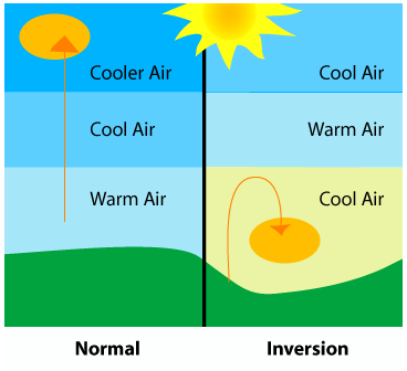 In the International Standard Atmosphere (ISA) the outside air temperature (OAT) decreases at a rate of 2 degrees per 1000 ft. In fact it’s not quite that simple, since the dry adiabatic lapse rate (DALR) is nearer 3?degrees/1000 and the saturated adiabatic lapse rate (SALR) nearer 1.5?degrees, so moist air rises less rapidly than dry, hence clouds that continue to build vertically while there’s high moisture content, hence the planet on which we live replete with clouds and rain and trees and forests and oceans and … but I digress.
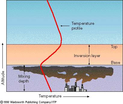
On top of this, weather characteristics and the geographical environment may affect the lower layer of the atmosphere to produce an increase in ambient temperature with ascent, rather than the expected (various degrees of) decrease. This is called a temperature inversion and down low, abbreviated as an LLTI.
The wikipedia entry is decent. For our purposes the basis of formation isn’t necessarily relevant, but we can look at two types for our purposes – Known and Unknown. The unknown kind can be half expected (based on local experience) but is rarely accounted for – it just comes as an annoyance on performance as your all-engines operating aircraft encounters it. The likelihood of an LLTI occurring at the exact same time as a critical engine failure with an obstacle constrained flightpath is so statistically remote that we can ignore it.
Or is that what we say about ATC and mid air collisions?
But when planning a takeoff with a known LLTI – usually reported by ATIS after pilot observation “Pilot reported Low Level Temperature Inversion of 15 degrees at 1000 ft” – you’re now planning on the loss of an engine when you hit this thing, which makes it somewhat more serious.
An LLTI for our purposes occurs at low level and rarely penetrates 2000 ft AGL. A 10 degree temperature inversion is considered quite significant and will usually be reported on the ATIS. Dubai is a prime location for LLTI’s where the ambient temperature is relatively high during the day but the ground cools quickly and significantly at night, setting up the conditions for a morning LLTI. I’ve flown through LLTI’s of 20 degrees (all engines operating) and the effect is noticeable – generally a marginal but detectable loss of performance. The fact that it usually hits just as you reduce to climb thrust, commence 3rd segment acceleration and occasionally as you reduce flap doesn’t help. But two engine performance is not the issue here and a LLTI will never be anywhere near the impact of actually losing an engine – just to keep things in perspective …
Performance Impact
All performance is based on density altitude and temperature is a key factor. The higher the temperature the higher the density altitude, the thinner the air and the less performance from your engines (and wings, etc). The key performance factor we’re interested in here is thrust from the engines, and since we’re usually talking about higher temperatures, it means we’re usually operating beyond the flat rating temperature of your engine. So we’d better start with that and talk about Flat Rating and Tref.
Flat Rating and Tref
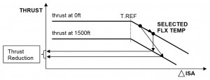
 For certification purposes – turbine engines are required to be able to produce a minimum fixed thrust throughout their operating life. This predictable thrust level is constant up to a certain ambient temperature – above this temperature the thrust produced by the engine is scaled back as OAT increases. The point at which thrust starts to reduce is known as the Engine Flat Rated Temperature (or Tref in Airbus speak) and is usually defined as an ISA deviation. For the GE90-115B engine the flat rating temperature is 30 degrees C at Sea Level (or ISA+15 degrees).
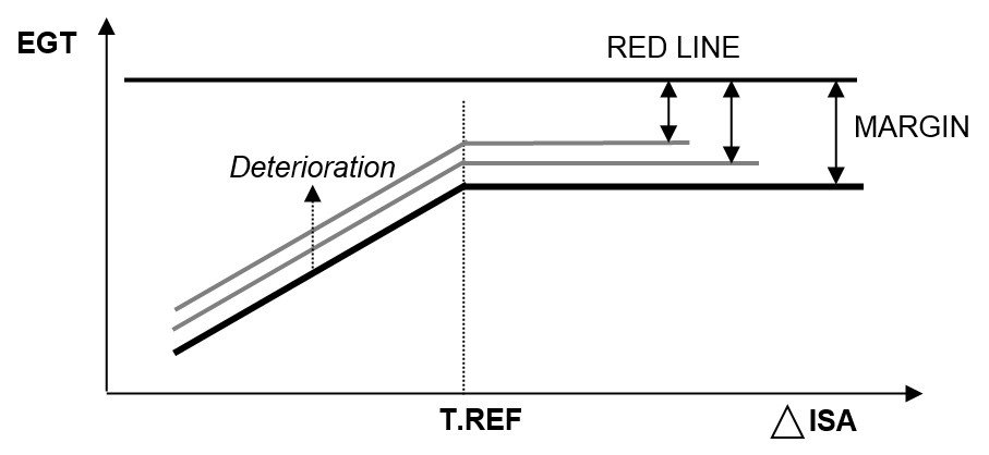
There should always be a margin between the thrust an engine is capable of producing and that required of it by scheduled takeoff performance. Below Tref this is defined by a pressure limit on the engine. Above Tref, it’s defined by a temperature margin, and can be loosely associated with the difference between the EGT achieved during the takeoff roll and the EGT the engine is limited to at Takeoff Thrust. The GE90-11B’s are unlimited at an EGT of 1050 degrees C and below (N1/N2 limits apply also), or with a 5/10 minute All Engine/Engine Out limit of up to 1090 degrees .
 Both above and below Tref – this translates broadly speaking to a margin below a critical exhaust gas temperature (EGT). In essence under ISA conditions a new engine will produce “maximum thrust” at a lower EGT than an engine at the end of it’s operating life.
For both of these engines, that “maximum thrust” is a pre-determined figure that your performance calculator has to be able to rely on. For a takeoff in excess of Tref, your performance computer counts on less and less thrust from the engine. A general rule of thumb is a loss of 0.75% thrust for each degree of temperature increase above Tref.
FADEC Thrust Setting
Another factor to bear in mind as we draw inexorably closer to actually discussing dealing with LLTI’s is thrust setting during takeoff. An engine with Full Authority Digital Engine Control (FADEC) continues to “tweak” the thrust set during the takeoff roll. Typically allowing for the increase in inlet pressure as the aircraft accelerates – in fact the N1 or EPR will be adjusted for a series of factors during the takeoff roll to produce a command parameter (N1/EPR) that results in the required thrust. When the ambient temperature increases on takeoff (instead of decreasing) it can be seen that the impact on thrust produced can be different depending on whether you’re above or below the Tref.
Watch the N1 during takeoff sometime – you’ll see it continue to change as the aircraft accelerates, even though the thrust levers are de-clutched in “HOLD”.
 N1 : Is not actually a parameter used directly for engine thrust management. N1 is corrected internally in the Electronic Engine Control (EEC) as a function of the TAT (depending on aircraft speed). This corrected N1 (referred to here on as N1-K) bears a direct relationship to thrust.
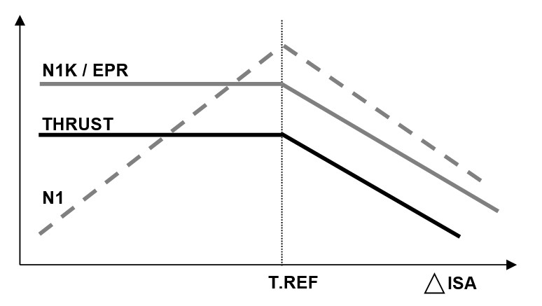
As temperature increases but remains below Tref, N1-K is constant with the thrust produced even as as N1 increases. In essence as the temperature decreases it requires more and more N1 to produce a constant thrust (N1-K). Unfortunately – we see N1, so I’ll keep N1 as a primary parameter for our discussion.
Ignoring the affects of increasing airspeed for a moment …
- Below Tref – as temperature increases, N1 increases to maintain a constant Thrust (N1-K)
- Above Tref – N1 will decrease with increasing temperature, as will Thrust (N1-K)
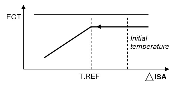 EGT is a little different. Power management is essentially established to maintain a constant EGT (in relation to a critical maximum EGT) above Tref. So below Tref, EGT will increase as OAT increases until OAT is at Tref, after which EGT will essentially remain constant with further OAT increases even as thrust decreases.
Ok, so we now have enough information to start looking at LLTI’s. If you’ve followed so far, you can see how we might choose to plan for a LLTI depends on the relationship between ambient OAT and Tref – remembering the B777-300ER’s GE90-11b engines are flat rated to 30 degrees C (or ISA+15).
During takeoff the EEC’s continuously compute N1 based on the current ambient temperature as sensed by the TAT probe at the top of the Engine Nacelle. Thus the effect of a LLTI on takeoff performance will depend on the type of takeoff being performed and on the magnitude of the temperature increase.
 LLTI; Maximum (or Fixed Derate) Thrust; Ambient below Tref
If you’re conducting a Maximum (or TO 1/2 derate) thrust takeoff with the ambient OAT below the flat rating temperature and a temperature increase occurs such that the ambient remains below Tref – the EEC’s will increase the N1 to maintain thrust required (N1-K constant) for the higher temperature. The EGT will increase but remain below maximum EGT.
Because this all takes place below Tref – there’s little impact on thrust. You may well still notice aerodynamic effects – but thrust loss is not one of them.
 LLTI; Maximum Thrust; Ambient above Tref

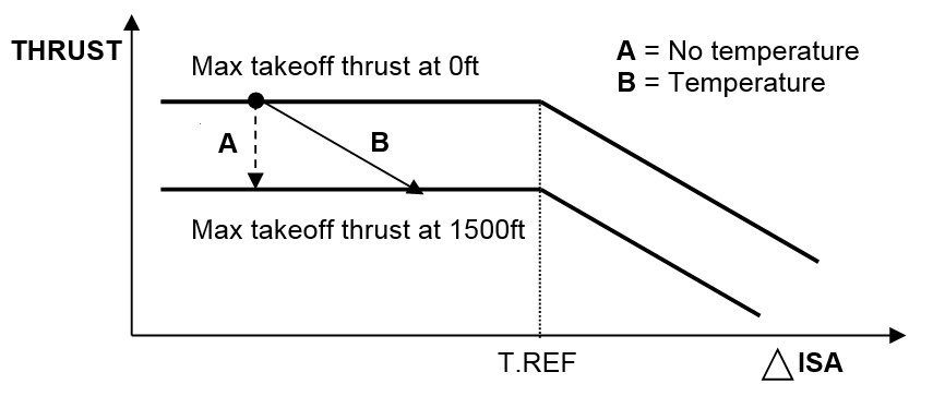
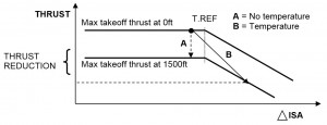
If your conducting a Maximum (or TO 1/2 derate) thrust takeoff and an OAT increase occurs that takes the ambient above Tref – the EEC’s will reduce N1 to maintain power management requirements rather than thrust required. This is the engine protecting itself to avoid an EGT exceedance. Thrust levels will reduce (compared to a “normal” takeoff) to maintain a constant EGT. The higher the OAT above Tref, the greater the reduction of thrust.
As a general rule, a temperature inversion of 10 degrees will result in a thrust reduction of about 10% (anywhere from 8% to 12% depending on the engine). However the loss of thrust applies at the maximum magnitude of the temperature inversion. Typically the temperature increase in an LLTI is uniform; thus the thrust reduction associated should also be uniform through the atmospheric LLTI.
LLTI; Assumed Temperature Takeoff
If you’re using assumed temperature with a temperature inversion, the following two cases have to be considered:
 If the OAT increase stays below the Assumed Temperature, then no effect on thrust will occur. The EEC’s will detect temperature and regulate thrust accordingly and not be limited by the Assumed value. Thrust will therefore remain constant compared to the standard atmosphere takeoff. You’ll see an increase in EGT due to the higher ambient; again you may notice aerodynamic effects – but thrust loss isn’t one of them.
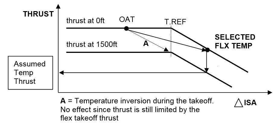
 If the temperature increase goes above the Assumed Temperature – then the assumed temperature solution is dropped by the FMC. The thrust solution reverts to maximum thrust (or max TO1 / TO2 thrust) and the implications are similar to the previous two situations – LLTI with Max Thrust above/below Tref. This scenario is less likely since it requires an already higher temperature on ground with a limited amount of reduced thrust and a temperature inversion higher than the difference between the OAT and the Assumed Temperature. Or is it?

That said, the situation in Abu Dhabi is actually quite close to what is being described here. A limiting takeoff where some derate (not much) is still available, where the ambient temperature is above the engine flat rating temperature – coupled with a report LLTI of 10 degrees or more. This sounds like a vintage Middle East morning departure.
Before we move on – it’s important to note that a temperature inversion during takeoff has little effect on engine performance when it occurs during Maximum/Derated/Assumed Thrust takeoff where the OAT is below Tref.
 Effect of an LLTI on Aircraft Performance

It should be clear now that for an LLTI to be a consideration on takeoff performance, the aircraft needs to be in the following scenario:
- Ambient temperature at or above Tref (30 degrees / ISA+15); or Ambient temperature plus LLTI temperature change in excess of Tref.
- Maximum Thrust (TO) or Max Thrust plus Assumed (TO-nn);
- Engine failure at V1; with an Obstacle constrained flight path (the runway will be behind you before you enter the LLTI);
- LLTI is such that it results in a regulatory net flight path margin cancellation and leads to compromised obstacle clearance.
In all other cases, even if performance is affected the result is a detrimental flight path lower than the nominal one, but clear of obstacles and minimum net flight paths.
It’s worth nothing that FAR/JAR Part 25 rules introduced conservatism to account for inaccuracies of the data used for performance calculation, and although not specifically mentioned, the case could be made that LLTI’s are part of in that consideration. There is however no specific documentation to state or imply this.
 The minimum climb gradient commencing at 35 ft above the runway for the second segment is 2.4% for a twin engine aircraft. Beyond this is a 0.8% margin between net and gross calculations. Typically a 10 degree LLTI over 1500 ft will halve the gross gradient between the planned/actual and net flight path if all else is equal. This implies that even with the LLTI the aircraft will remain clear of obstacles.
However the LLTI affected flight path is a curve, with performance continuing to degrade the higher and further the aircraft goes until it reaches a point where the aircraft will be below the net flight path. However LLTI’s are usually relatively shallow in nature, with a more normal atmosphere prevailing above which would restore climb performance to the aircraft.
What To Do?
If you don’t expect the engine to fail – LLTI’s are not a consideration. The combination of an engine failure with an LLTI of more than 10 degrees is extremely remote, which is perhaps why regulatory authorities have never addressed this issue. Hence we tend to ignore the possibility of unknown LLTI’s.
It’s somewhat different when you’re the Captain, and the ATIS says you have an LLTI over the airport, that probability has just been increased to 100% – now you’re back catering for an exceedingly unlikely engine failure into a known LLTI.
It should be clear now that when the ambient is below Tref; when there a healthy derate (assumed or otherwise); when there are no obstacles on departure – the LLTI is a consideration, but not a limiting one, or one that would result in a change in takeoff performance calculation.
Note that the use of TO1 or TO2 implies that if needed you can advance the thrust to full TO in the event of degraded performance. You’ll want to make sure you’re not operating in the low weight/low speeds part of the envelope where control can be compromised by full thrust in respect of VMCA/V2.
 Therefore let’s address the specific scenario of concern as follows and suggest a recommendation.
- Ambient temperature at or above Tref (30 degrees); or Ambient temperature plus LLTI temperature gradient in excess of Tref.
- Maximum Thrust (TO) or Max Thrust plus Assumed (TO-nn);
- Obstacle constrained flight path;
- LLTI is such that it’s likely to result in a regulatory net flight path margin cancellation leading to compromised obstacle clearance (at least 10 degrees)
If this is your scenario one possibility is to add the temperature inversion value to your OAT in order to correct the temperature used in performance calculations. For older engines that are EGT limited at higher thrust settings – this will recover some of your lost margin against EGT redline. If you’re using assumed thrust – you can still do this as long as the inversion does not exceed the assumed temperature value.
As with all such recommendations – this is only a real decision when it comes to a payload limited departure. It’s the Captain’s decision on the day to offload cargo and/or passengers and bags against the possibility of an engine failure combined with a reported LLTI and an obstacle critical flightpath. It’s worth emphasizing again that there’s no regulatory basis/requirement for this, even though there is no doubt that temperature inversions have a direct effect one engine and aircraft performance during climb.